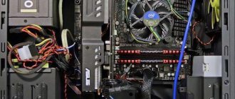
Mining involves the use of several devices that perform calculations independently of each other and are arranged on one motherboard. In this case, the power supply for mining must have the appropriate power, which will allow powering all devices. A good option would be to use power supplies with high power, but not all of them can be used when assembling a mining farm. This is due to the fact that under normal conditions several video cards are not used, so power supply manufacturers did not provide a large number of similar outputs, and the power provided by the motherboard is also limited.
Even using motherboards designed specifically for mining does not guarantee sufficient power for each mining device. When mining on 6 video cards, the power supply must have a sufficient number of 6 pin or 6 pin+2 outputs, have a reserve of at least 10% above the maximum power consumed by all devices, and be reliable enough to operate around the clock. It is possible to use splitters that provide connection of several devices to one output, but in this case the load on it increases significantly and can lead to failure of the entire power supply.
Server power supplies
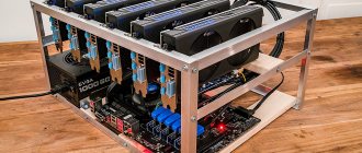
Home GPU mining rigs use 4 or more video cards, each of which consumes from 30 to 300 W. To ensure their uninterrupted operation, server power supplies that are reliable and have the necessary power are often used.
The server version is much more powerful than its regular ATX counterparts, but it can heat up to higher temperatures and operate much louder.
Noisy coolers are one of the disadvantages of such devices, however, reliability, which allows them to work around the clock at maximum loads, allows us to neglect this inconvenience. At the same time, the price for them ranges from 8,000 to 60,000 rubles, which is not affordable for every miner.
The number of outputs suitable for providing video cards with 12V power limits the application. Purchasing several splitters expands the capabilities of the power supply, but you should not exceed the maximum power of the outputs, as this may lead to equipment failure.
Some craftsmen carry out wiring of additional outputs, but this requires knowledge and skills to perform the operation without damaging the equipment. The price of a soldered server power supply will be slightly higher than the standard configuration, but will avoid unnecessary problems.
It is necessary to carefully calculate the power consumed by video cards, take into account that video cards are partially powered through the PCI-E port, and calculate the additional power supplied. It is necessary to take into account the maximum current strength on the additional power wires; it determines how many video cards the power supply can simultaneously pull without overheating.
The load on the 6 pin or 6 pin+2 outputs is calculated by summing the power consumption of the powered devices and subtracting the power supplied through the PCI-E ports. Through a PCI-E port, up to 75 W can be supplied to the video card, which must be subtracted from the maximum declared power. A server power supply used for mining is usually capable of powering 4 to 8 video cards.
⇡#Active PFC block
In an AC circuit with a linear load (such as an incandescent light bulb or an electric stove), the current flow follows the same sine wave as the voltage. But this is not the case with devices that have an input rectifier, such as switching power supplies. The power supply passes current in short pulses, approximately coinciding in time with the peaks of the voltage sine wave (that is, the maximum instantaneous voltage) when the smoothing capacitor of the rectifier is recharged.
Current consumption of a switching power supply
The distorted current signal is decomposed into several harmonic oscillations in the sum of a sinusoid of a given amplitude (the ideal signal that would occur with a linear load).
The power used to perform useful work (which, in fact, is heating the PC components) is indicated in the characteristics of the power supply and is called active. The remaining power generated by harmonic oscillations of the current is called reactive. It does not produce useful work, but heats the wires and creates a load on transformers and other power equipment.
The vector sum of reactive and active power is called apparent power. And the ratio of active power to total power is called power factor - not to be confused with efficiency!
A switching power supply initially has a rather low power factor - about 0.7. For a private consumer, reactive power is not a problem (fortunately, it is not taken into account by electricity meters), unless he uses a UPS. The uninterruptible power supply is responsible for the full power of the load. At the scale of an office or city network, excess reactive power created by switching power supplies already significantly reduces the quality of power supply and causes costs, so it is being actively combated.
Electrical diagram and current consumption of the Active PFC unit
In particular, the vast majority of computer power supplies are equipped with active power factor correction (Active PFC) circuits. A unit with an active PFC is easily identified by a single large capacitor and inductor installed after the rectifier. In essence, Active PFC is another pulse converter that maintains a constant charge on the capacitor with a voltage of about 400 V. In this case, current from the supply network is consumed in short pulses, the width of which is selected so that the signal is approximated by a sine wave - which is required to simulate a linear load . To synchronize the current consumption signal with the voltage sinusoid, the PFC controller has special logic.
The active PFC circuit contains one or two key transistors and a powerful diode, which are placed on the same heatsink with the key transistors of the main power supply converter. As a rule, the PWM controller of the main converter key and the Active PFC key are one chip (PWM/PFC Combo).
Active PFC block and input rectifier (Antec VP700P)
The power factor of switching power supplies with active PFC reaches 0.95 and higher. In addition, they have one additional advantage - they do not require a 110/230 V mains switch and a corresponding voltage doubler inside the power supply. Most PFC circuits handle voltages from 85 to 265 V. In addition, the sensitivity of the power supply to short-term voltage dips is reduced.
By the way, in addition to active PFC correction, there is also a passive one, which involves installing a high-inductance inductor in series with the load. Its efficiency is low, and you are unlikely to find this in a modern power supply.
Synchronized power supplies
Buying one power supply with enough power to operate a mining rig is much more expensive than using a pair of low-power devices. There are two ways to connect two power supplies to one computer:
- When you turn on the computer, both devices start up simultaneously. At the same time, each of the blocks provides power to part of the system, ensuring uninterrupted operation. For this purpose, special devices are used that allow synchronizing two power supplies, or soldering wires in a certain order with connecting a relay.
- An additional power supply powers mining devices (video cards) and turns on independently of the main one. The launch is forced and does not in any way affect the operation of the main unit, which supplies power to the motherboard, hard drive, RAM, coolers and some video cards.
The second method is much simpler, but it does not ensure simultaneous operation of all devices and the power supplies operate independently of each other. To force a start, you will need to connect the wires responsible for the start together. On the 24-pin connector on the side of the lock, the 3rd and 4th wires on the right (usually green and black) are counted, which are responsible for the forced start of the power supply. In the simplest case, it is enough to connect them together with a piece of insulated wire, inserting it into the indicated connectors.
The power supply will be started using the button located on the back or by connecting the pilot (power cord) to the network. Using a release button will make starting easier and more convenient. In this case, using a soldering iron, the required length of wires is added to the above contacts, and the button is placed in a convenient place in the farm body. The additional power supply starts from this button and works independently of the main one.
The synchronization method is much more reliable and will allow simultaneous start-up of several (possibly more than 2) power supplies. To do this, select the main power supply, which gives a signal to start the second power supply. The synchronizer allows you not to have to worry about wiring and selecting the required relay. The cheap price and factory execution will allow you to avoid errors when connecting by soldering.
The photographs below show options for such devices.
№1:
№2:
Depending on the model, there are options that allow you to run additional video cards directly from the synchronizer; in other cases, only the outputs located on the power supply are used. The top photo shows that you can solder a couple more 8-pin connectors to the board and use them fully.
The 24-pin main power supply is connected to the motherboard, the slave power supply is connected to the synchronizer. The molex connector is used to receive the trigger signal and is connected to the main device.
The big disadvantage of schemes with two power supplies is the lack of short circuit protection, which will lead to failure of video cards and other mining devices. The use of an uninterruptible power supply or other devices that completely disconnect the system from the network during overloads will allow you to maintain the functionality of the equipment if one power supply fails.
Video - description of the synchronizer and the principles of its operation:
Video - connecting two power supplies via a synchronizer:
For CPU
Processor performance has been steadily increasing in recent decades. Their energy consumption is also growing. The processors are powered by voltage converters (VRMs) installed on the motherboard. About two decades ago, there was a massive transition in VRM power supply from +5 volts to +12 volts. This is due to the fact that less current is required to transmit the same power at a higher voltage. VRMs receive power via a separate cable with a 4-pin connector. Two contacts are for +12 volts (yellow wire) and two are for ground (black insulated wire).
Connector for VRM 4 pins.
The sockets on the connector and the pins on the board are arranged in two rows according to their intended purpose. Two pins serve as a key - their shape is different from the others, so an erroneous connection is impossible.
Pinout of 4-pin connector for VRM.
As productivity increased, the number of VRMs began to grow (first on servers, then on personal computers), so the question arose about rational power distribution. The issue was resolved by using 8-pin connectors. In them, the supplied power is distributed over 4 pairs of conductors.
Connector for VRM 8 pins.
Otherwise, there are no fundamental differences from the previous version. The connector contains two rows of sockets - +12 volts and 0 volts, only 4 in a row.
Pinout of 8-pin connector for VRM.
Progress cannot be stopped; energy consumption by processors will only increase. It looks like 4-pin connectors have outlived their usefulness and are becoming a thing of the past.
For video card (PCI Express)
Video cards of previous generations, which have low performance, and modern budget-class models are powered by the PCIe x 16 connector to which they are connected. The voltage to this terminal comes from the motherboard, which, in turn, is powered from the power supply through a 24(20)-pin connector. This is enough to transmit 75 watts.
PCI Express additional power connector.
This is not enough for modern high-performance cards, so they are provided with an additional PCI Express power input. Initially, it was a 6-pin connector and allowed for additional power supply of 75 watts. Very soon this bandwidth was not enough, and subsequent ATX standards were supplemented by an 8-pin connector and 120 watts.
Pinout of 6-pin and 8-pin connector.
This connector is also available in a universal 6+2 format, allowing it to be used for both 6-pin and 8-pin video card connectors.
Universal connector 6+2.
For the most modern video cards, manufacturers use connectors with twelve pins , but they are not yet widely used.
For hard drives and other devices (SATA, MOLEX)
To connect hard drives and some other peripherals, the Molex connector (named after the manufacturer) has been used for a long time. Its advantage is that it has plugs and sockets with large, powerful contacts that operate reliably at high currents.
The plug-in elements are arranged in one row. The connector also has a key to prevent incorrect connections. The two inner pins are for ground wires (black). Conductors with a voltage of +5 volts and +12 volts are connected to the extreme ones. Each contact is designed for a current of 11 amperes, which allows you to transmit 55 watts through a five-volt channel, and 132 watts through a twelve-volt channel. The pinout of the Molex connector is shown in the figure.
Molex connector pinout.
The power transmitted along the power line is limited not only by the load capacity of the connector, but also by the cross-section of the wires of the connected cable, the width of the printed circuit board tracks, etc. To determine the highest power of the line, it is necessary to select the capabilities of the least powerful component.
Due to the increased popularity of the SATA standard, Molex connectors are being replaced by SATA power connectors, which have 15 outputs. 3 pins are used for each voltage, which allows you to transmit more power without increasing the cross-section of the conductors and maintaining the flexibility of the cable. The voltage groups are separated by groups of neutral wires (3 conductors each). The connector pinout is in the table.
| Contact number | Wire color | Voltage level, V |
| 1 | Orange | +3,3 |
| 2 | Orange | +3,3 |
| 3 | Orange | +3,3 |
| 4 | Black | 0 V |
| 5 | Black | 0 V |
| 6 | Black | 0 V |
| 7 | Red | +5 |
| 8 | Red | +5 |
| 9 | Red | +5 |
| 10 | Black | 0 V |
| 11 | Black | 0 V |
| 12 | Black | 0 V |
| 13 | Yellow | +12 |
| 14 | Yellow | +12 |
| 15 | Yellow | +12 |
The SATA standard involves connecting devices with two connectors - for power and for data transfer. They should not be confused.
SATA power connector.
What block power is needed for mining?
Based on the fact that the power supply will be operated around the clock in hard mode, you need to use a power supply that has both the necessary power reserve and take into account the fact that over time, electronic components age and the actual output power of the power supply decreases.
In addition, it is necessary to take into account the fact that any electrical circuits are nonlinear and at the moment of switching on and off, peak currents flow through them, higher than in operating mode. In this regard, a power reserve in the power supply for mining is so necessary. Simply installing the most powerful power supply on existing equipment is not always the best solution due to the fact that, as a rule, power supplies have the best efficiency when loaded at 50-60 percent power. If the power supply is underloaded, it will not work efficiently, and in some cases it may simply not start. Therefore, you need to know how to correctly calculate the power of the power supply.
Cleaning and Maintenance
Due to the constant operation of the power supply fan, it forces a large amount of air through its case. This dust-containing air clogs the power supply case over time, which significantly worsens its temperature. May cause fire or malfunction. To avoid wasting time on repairs, it is advisable to periodically clean them. By blowing, and in case of heavy contamination by disassembling and cleaning with an antistatic brush.
Weekly purging is mandatory. To avoid spending a ton of money on cans of compressed air, buy an electric leaf blower. But no matter how hard you try, dust will still settle and stick, so sooner or later more thorough cleaning will be needed.
If the device is still under warranty, then it is better not to open it yourself, but contact a specialized service center. As they say: “Cleanliness is the key to health,” and in this case, the key to timely receipt of profit. Happy mining!
⇡#Secondary circuit
The secondary circuit is everything that comes after the secondary winding of the transformer. In most modern power supplies, the transformer has two windings: 12 V is removed from one of them, and 5 V from the other. The current is first rectified using an assembly of two Schottky diodes - one or several per bus (on the highest loaded bus - 12 V - in powerful power supplies there are four assemblies). More efficient in terms of efficiency are synchronous rectifiers, which use field-effect transistors instead of diodes. But this is the prerogative of truly advanced and expensive power supplies that claim the 80 PLUS Platinum certificate.
The 3.3V rail is typically driven from the same winding as the 5V rail, only the voltage is stepped down using a saturable inductor (Mag Amp). A special winding on a transformer for a voltage of 3.3 V is an exotic option. Of the negative voltages in the current ATX standard, only -12 V remains, which is removed from the secondary winding under the 12 V bus through separate low-current diodes.
PWM control of the converter key changes the voltage on the primary winding of the transformer, and therefore on all secondary windings at once. At the same time, the computer's current consumption is by no means evenly distributed between the power supply buses. In modern hardware, the most loaded bus is 12-V.
To separately stabilize voltages on different buses, additional measures are required. The classic method involves using a group stabilization choke. Three main buses are passed through its windings, and as a result, if the current increases on one bus, the voltage drops on the others. Let's say the current on the 12 V bus has increased, and in order to prevent a voltage drop, the PWM controller has reduced the duty cycle of the key transistors. As a result, the voltage on the 5 V bus could go beyond the permissible limits, but was suppressed by the group stabilization choke.
The voltage on the 3.3 V bus is additionally regulated by another saturable inductor.
Stabilizing chokes and output filter (Antec VP700P)
A more advanced version provides separate stabilization of the 5 and 12 V buses due to saturable chokes, but now this design has given way to DC-DC converters in expensive high-quality power supplies. In the latter case, the transformer has a single secondary winding with a voltage of 12 V, and the voltages of 5 V and 3.3 V are obtained thanks to DC-DC converters. This method is most favorable for voltage stability.
DC-DC converter for 5 V bus (CoolerMaster G650M)
Output filter
The final stage on each bus is a filter that smoothes out voltage ripple caused by the key transistors. In addition, the pulsations of the input rectifier, whose frequency is equal to twice the frequency of the supply network, penetrate to one degree or another into the secondary circuit of the power supply.
The ripple filter includes a choke and large capacitors. High-quality power supplies are characterized by a capacitance of at least 2,000 uF, but manufacturers of cheap models have reserves for savings when they install capacitors, for example, of half the nominal value, which inevitably affects the ripple amplitude.
Producer groups
- OEM (Original Equipment Manufacturer) – companies that design and manufacture units.
- Companies that do not have their own production, these companies can develop the design or software, but OEM partners produce blocks for them. Such companies include: Corsair, Be Quiet, SilverStone. For example, for Corsair the OEM of the HXi series power supplies is CWT.
- And the third category is TradeMark (™) companies, they simply label the purchased products with their own brand and resell them on the market, perhaps slightly changing the design of the radiator.
In our case, we will choose power supplies from 750 watts and above. To run one farm with 5 video cards from Sapphine Nitro+ RX 480 8GB, we need one good 1200-watt power supply, or two 750-watt power supplies.